| |
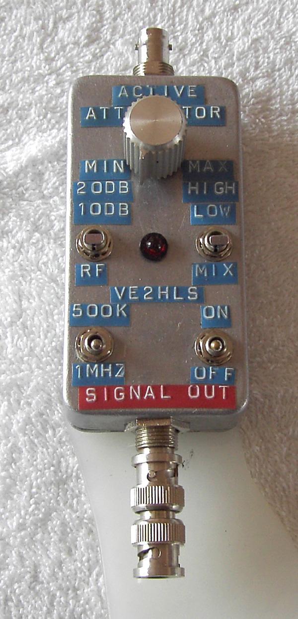
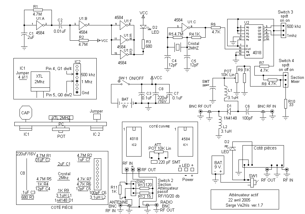
The active attenuator helps
to reduce the FM signal when you are closing in on the transmitter. When
you get really close to a transmitter the signal is so strong that it will
come in by the front end of your radio even with no antenna. This
project has one 2 Mhz crystal, two CMOS , one 4584 and one 4018. The first
one a HEX Smichtt Trigger makes the crystal oscillate and also makes the
led flash, the second one is a divisor giving the hunter a multiple choice
of frequency. So you can choose to listen to the transmitter at a
lower or higher frequency, the offset can be 200, 250, 500 ou 1 Mhz, make
your choice. Most of the time we select 500 Khz or 1 Mhz. Two
more options are possible, a mixer section putting the RF signal to ground
with a toggle switch and another section
giving you a passive attenuator of 10 and 20 DB. |
| |
|
Attenuator
schematic |
|
|
|
 |
 |
|
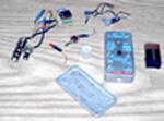
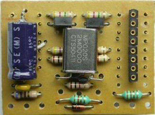
All parts |
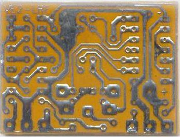
The PCB is
not drilled yet |
|
|
|
 |
 |
|
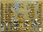
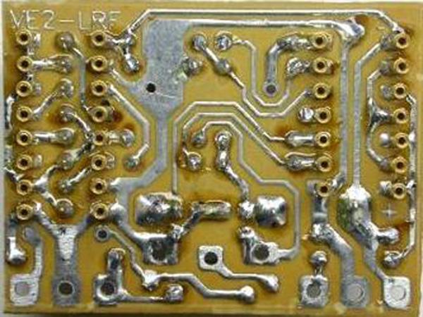
The holes are made. |
Remark :
Both sockets are soldered on the copper side. |
|
|
|
|
|
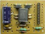
Active attenuator parts list.
C1 - 2.0 µF
C2 - 0.01 µF
C3, C7 - 0.1 µF
C4, C5 - 12 pF
C6 - 100 pF
C8 - 220 µF 16V
Surface Mount 220pF
D1 - 1N4148
D2 - Led
L1, L2 - 3.1µH
Pot 10k linear
R1, R2 - 4.7 Meg
R3 - 680 ohms
R4, R9, R11 - 1k
R5 - 4.7 Meg
R6, R7, R8 - 4.7k
R10 - 33 ohms
R12 - 15 ohms
R13 - 120 ohms
Crystal 2 MHz
Battery 9V
Wire for the 9V. battery
Switches
SW1, SW3 - on/off : Single pole, Single Throw
SW2, SW4 - on/off/on : Single pole, Double Throw
IC
U1 - 4584
U2 - 4018
Machined sockets
14 pins, 16 pins
1
aluminium box width 2 3/8" X lenght 4 3/8" X height 1 1/4"
1 knob for the potentiometer
2 BNC connectors.
1 plexiglas 1/8" x width 3 1/2" x lenght 12" for supporting the radio and
the attenuator. |

