|
Building a workshop Power Supply |
|
by Jacques VE2EMM |
 |
| It all started following a need for my workshop, I began this project in 1973, I had found an outline of circuit in the Circuit Cellar magazine. It took me several years to get it going nicely. |
| The cost can vary between $0 and $50 according to the size of your junk box. |
| With a maximum capacity of 20 volts and 1 amp, it will supply most of your projects, it's greatest quality is the protection all your projects, it is capable of limiting the maximum current to as low as 1mA, saving your ICs and transistors in case of an accidental short circuit during the experimenting period of your projects. It is also an excellent battery charger. |
|
The main parts : |
| Using an old LM723 (30 years) can seem antiquated, but it's still the most precise of the variable regulators. The precision is due to the internal reference voltage of 7 volts. By applying this reference to the one of the input of the error amplifier and the other input to a voltage coming from the output of the supply, the smallest deviation will make the output of the amplifier go + or - to control the output voltage of the supply. |
 |
| Let's replace the old current transistor 2N3055 by a Darlington transistor TIP142. This transistor as a gain of 1000, so it requires only 1 mA to supply 1 Amp. The original 2N3055 which was used had a gain of 10. The TIP142 is protected by a diode witch prevents its destruction in case of an inverted voltage applied at the output, it's internal resistors R1 and R2 allows him to reduce the output current rapidly to 0, by dissipating the excess loads at his base. |
 |
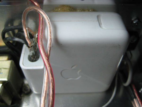
| The power supply can be a
laptop power supply or a transformer with a diode bridge and a electrolytic capacitor. I used an old Apple laptop power supply (24VDC @ 1.87A). The source must have at least 3 volts more than the voltage required at the output. |
 |
|
Description of the circuit : |
| The 7 volts reference at pin 6 of the 723 voltage controller is divided by two (3V) and applied to pin 4 witch is an inverting input, we can see that resistances R11 and R8 pass a current of 1 mA (I=E/R or 1mA=7V/7K), this voltage (pin4) is compared to the non-inverting pin 5. We must also maintain 1mA in the circuit at the non-inverting pin, this is done by resistance R 10, R 9, and VR02, if we maintains 1mA, VR02 will gives 1V drop for each 1000 Ohms, therefore 20K = 20 Volts. |
| The current limiter 723
function in the same way, but it measures 1V max, the resistor which measures the current R02 is selected to give 1V at the maximum current. Notice that R01 has a value of 1K. The output pin 9 of the current limiting device controls the input CL of the 723 to close it if necessary and to limit the current to the selected value. |
 |
|
Building the supply : |
| The layout of the circuits is not critical, using a PC Board will facilitate construction. The TIP142 can dissipate 24W at his maximum and we must use a heat sink. I used a heat sink that I took from an old PC. |
 |
|
Conclusion : |
| Using a variable supply with a limiting current capacity facilitates the experimentation of electronic circuits. It can also charge batteries of all kinds: Lead, NiMH, NiCd, Li-ion. |
| All the documentation of the presentation (14.3 meg) |