|
|||
|
Doppler Home Antenna |
|||
|
Pictorial : Doppler Home Antenna |
|||
 |
|||
|
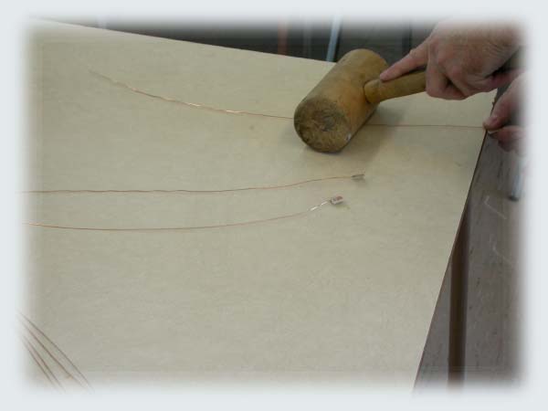
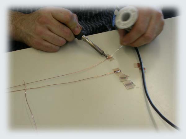
Use #22 copper wire for dipoles. |
|||
|
|
|||
|
Stretch and straighten the wire removing folds. |
|||
|
|
|||
|
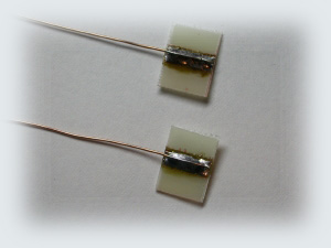
Solder dipoles to small PC Board and insert into PVC pipes. |
|||
 |
|||
|
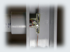
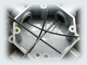
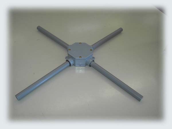
The switcher goes in the center of the waterproof cross. |
|||
 |
|||
|
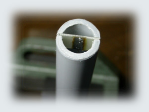
Use four old TV ferrites 75 to 300 ohms as baluns between the dipoles |
|||
|
and the coaxes (RG-174). |
|||
|
|
|||
|
Solder coaxes to dipoles. The coaxes are ready for the switcher. |
|||
|
|
|||
|
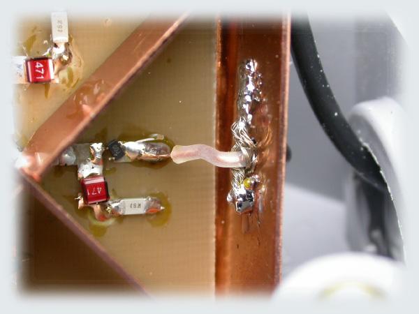
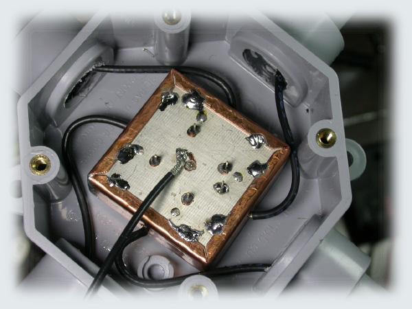
The coaxes (RG-174) are soldered to the switcher. |
|||
|
|
|||
|
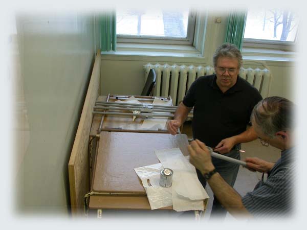
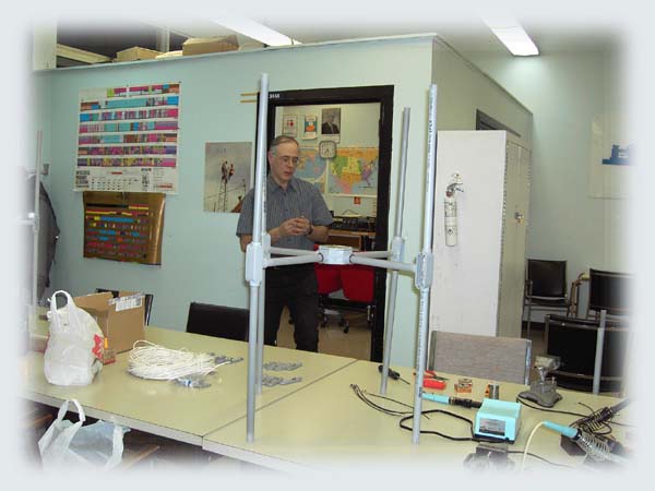
The parts are assembled, Serge VE2HLS and Michel VE2MAA |
|||
|
|
|||
|
Eagle Eye Jean VE2JMK! |
|||
 |
|||
|
Busy, busy, Michel VA2MAA |
|||
|
|
|||
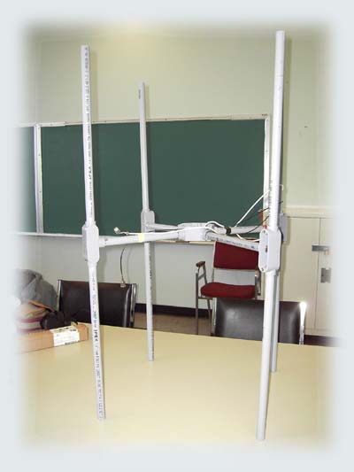
| The antenna is almost completed. Only 8 caps need fitting at ends of pipes. | |||
 |
|||
|
The cover and the antenna are completed. |
|||
 |
|||
|
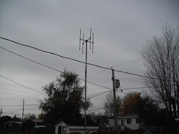
The completed antenna. |
|||